|
|
When managing connectors with extensive pin counts, spatial clarity and data density are critical. The updated insertion logic provides the tools necessary to handle complex components with precision.
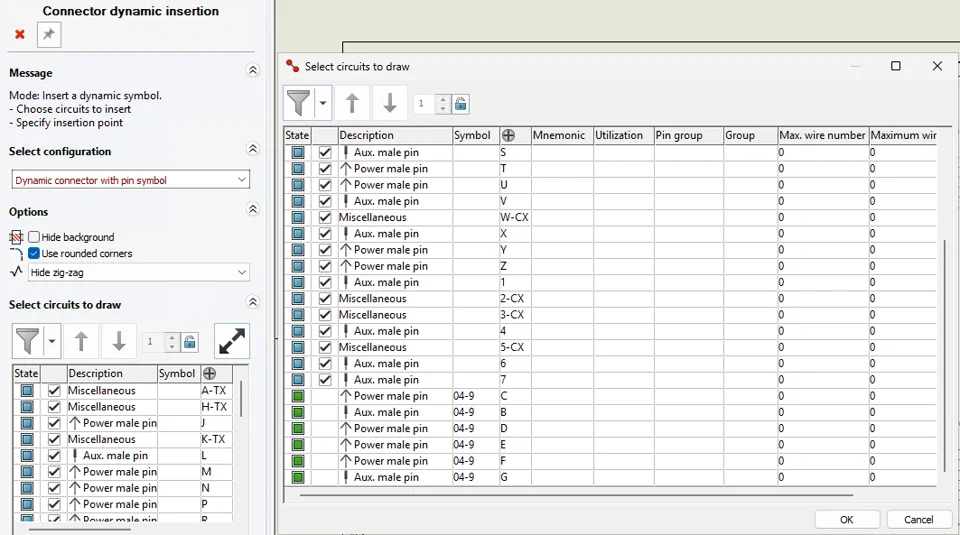
Enhanced “Insert Connector” Interface: The legacy side panel for Dynamic Connector insertion has been redesigned for superior usability. A new filter button opens a dropdown menu with specific visibility options: <All>, Not Inserted, Selected, and Not Selected.
Independent Selection Dialog: A new, scalable interface can be launched directly from the side panel. This provides a high-density, granular view of circuit groups, wire sections, and the maximum wire count.
Logical Sorting & Visualization: To prevent pin-assignment errors, the system enforces a hierarchical sort:
Symbol Association: Groups circuits by their assigned symbol.
Internal Order: Follows the symbol and manufacturer part definitions.
Visual Validation: Circuits are color-coded (Green for inserted, Blue for available), providing immediate feedback on connector population status.
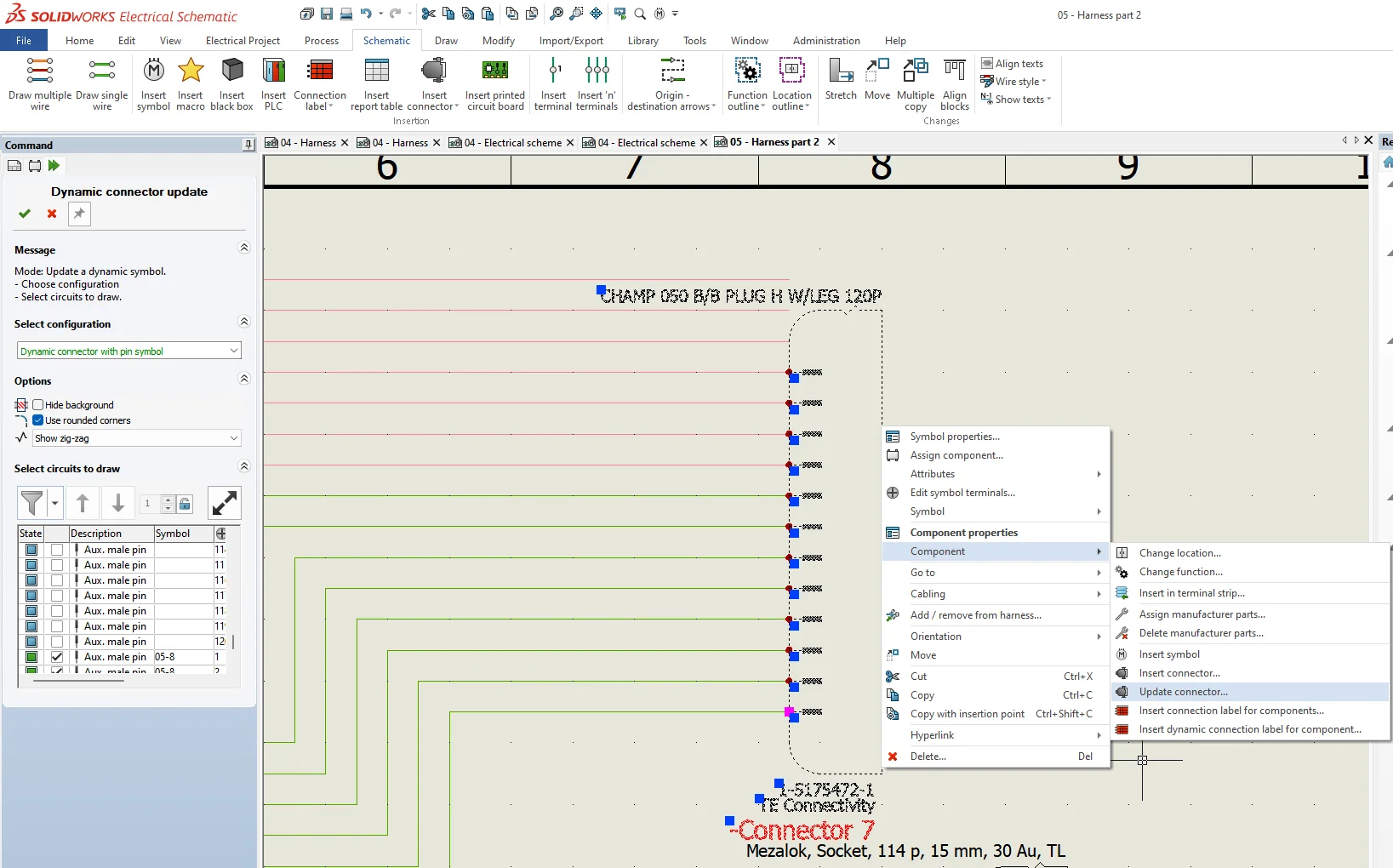
The most significant advancement regarding dynamic connector is the transition away from the “delete and re-insert” cycle. The new Update Dynamic Connector command enables real-time modifications while preserving the integrity of the design.
Preserve Wiring Intelligence: When a connector layout is modified, the system maintains existing wire connections. This eliminates the risk of losing connectivity data during a revision.
Dynamic Re-sequencing: Engineers can now add, remove, or reorder pins within a placed symbol using simple drag-and-drop actions.
Visual Adaptability: Post-placement adjustments—including zigzag patterns and corner configurations—can be updated without affecting the underlying electrical logic.
To bridge the gap between schematic design and the shop floor, SOLIDWORKS Electrical provides deep-tier manufacturing data through Accessory Association in complement with dynamic connector functions. This ensures every physical component—seals, plugs, and pins—is accounted for in the final build.
Manufacturing Associations: Accessories can be linked to specific circuits or terminals, ensuring the digital twin matches the physical assembly requirements.
Reusable Electrical Assemblies: These complex relationships can be saved in the library as Electrical Assemblies. This allows engineers to reuse fully defined, “ready-to-build” connector setups across multiple projects, ensuring 100% BOM accuracy and consistent manufacturing outputs.

|
|
 |小黑屋|手机版|Archiver|机械荟萃山庄
( 辽ICP备16011317号-1 )
|小黑屋|手机版|Archiver|机械荟萃山庄
( 辽ICP备16011317号-1 )


 发表于
发表于